
PlayStation Vita has long been Sony’s last portable gaming console. However, over time, some parts of these devices wear out. In this post, I’ll explain how I replaced the joysticks on my PS Vita Slim (PCH-2000 series). It only requires removing a few screws and no soldering, so we can call it a “drop-in” replacement.
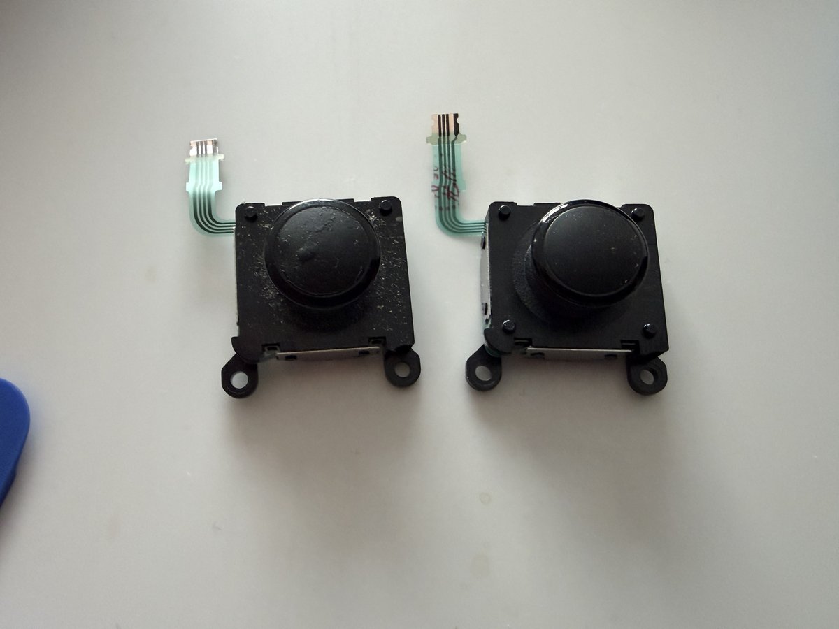
The rubber coating on the PS Vita’s analog joysticks can chemically degrade over the years, becoming sticky. This is called “Rubber Reversion” and it’s a common issue found in many older electronic devices.
Temporary Solutions:
– Isopropyl Alcohol (IPA): Wiping with 99% IPA helps to some extent, temporarily reducing the stickiness
– Baby Powder: A temporary solution that masks the stickiness by drying the surface
– Silicone Spray: Creates a protective layer but isn’t a long-term solution
As a result, since these temporary solutions didn’t provide satisfactory results, I decided to completely replace the joystick modules.
Required Materials:
– New PS Vita Slim joystick modules
– Phillips screwdriver (#00)
– Plastic opening tools (spudger/pry tool)
– Tweezers
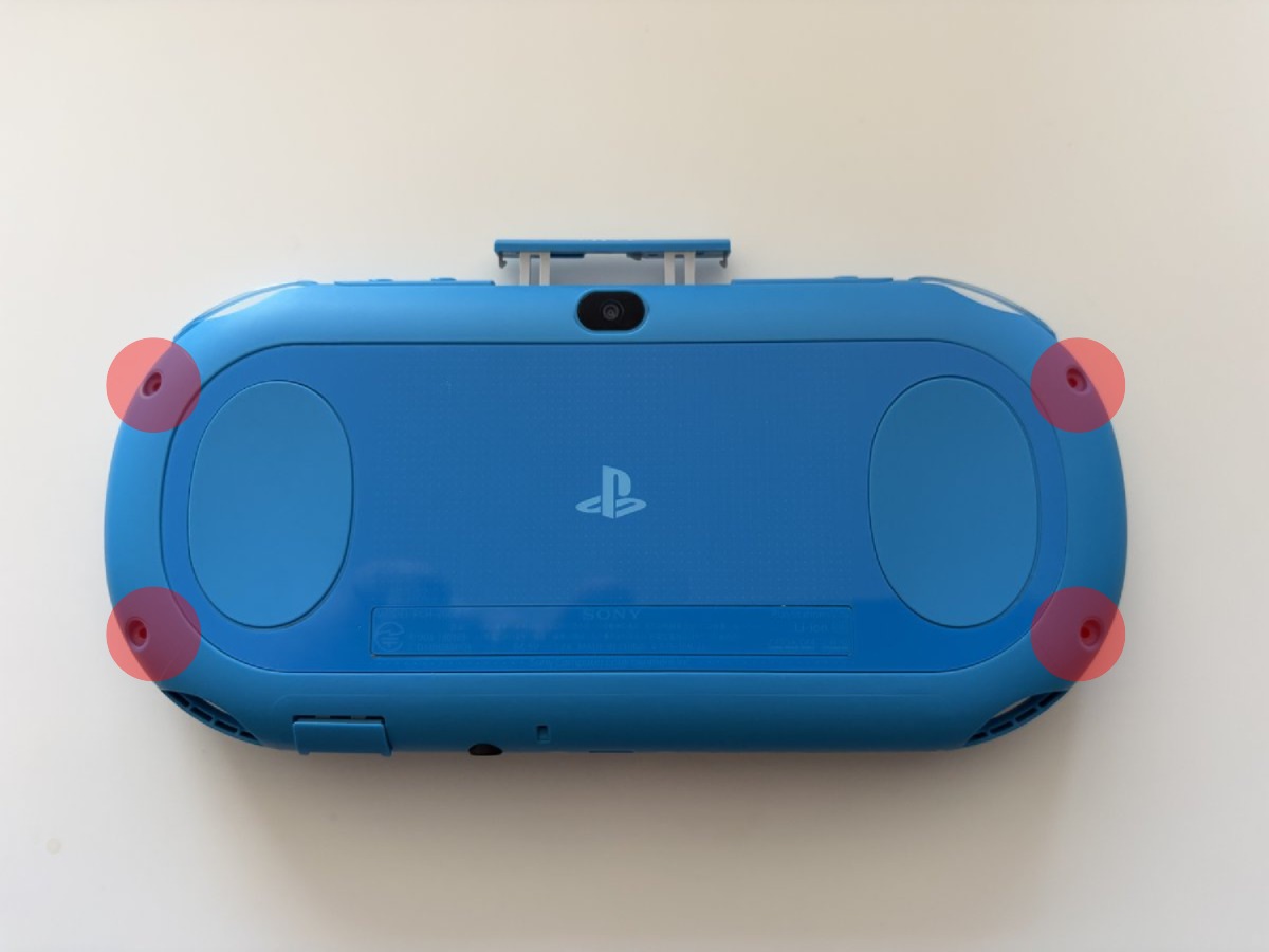
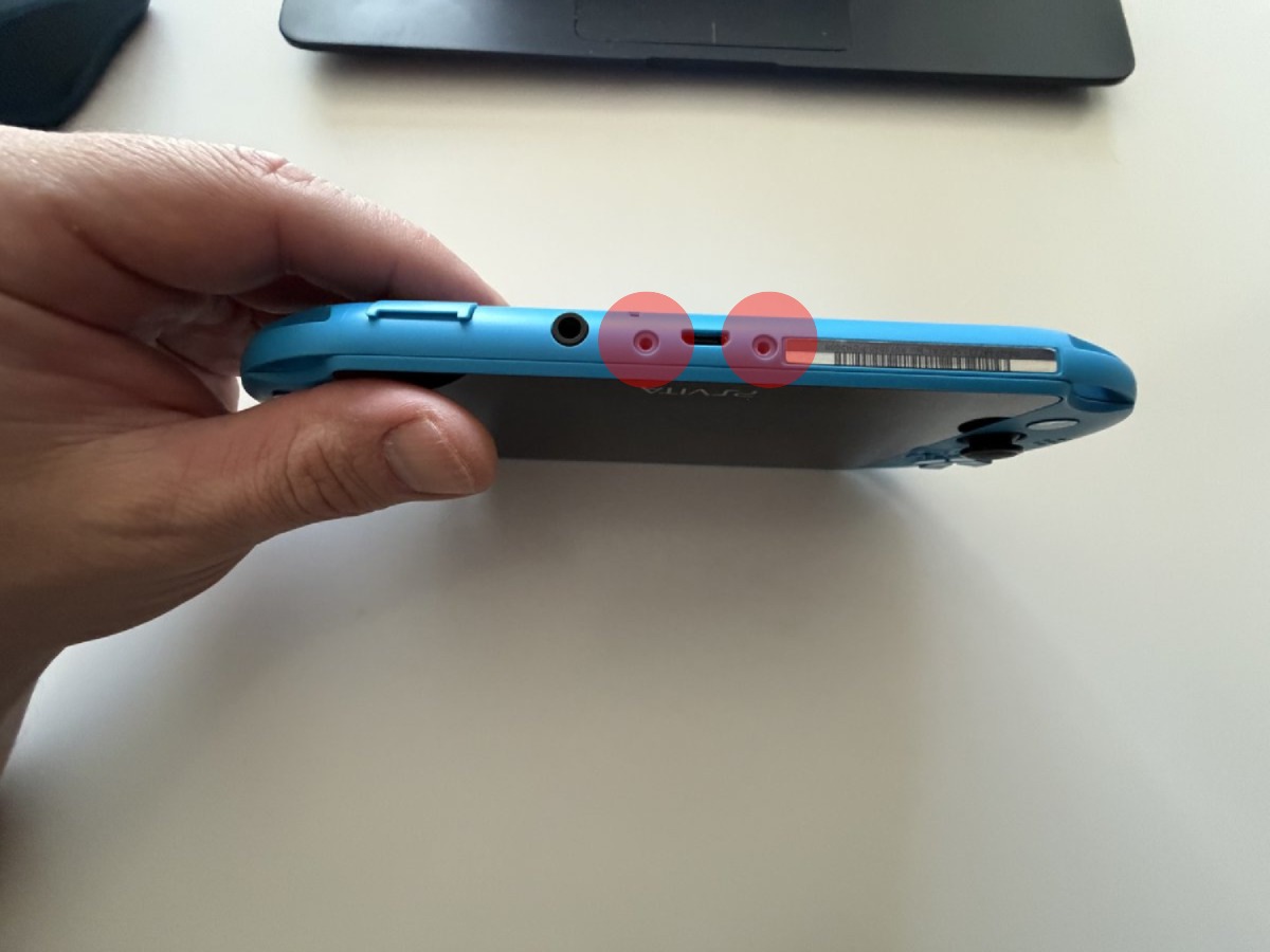
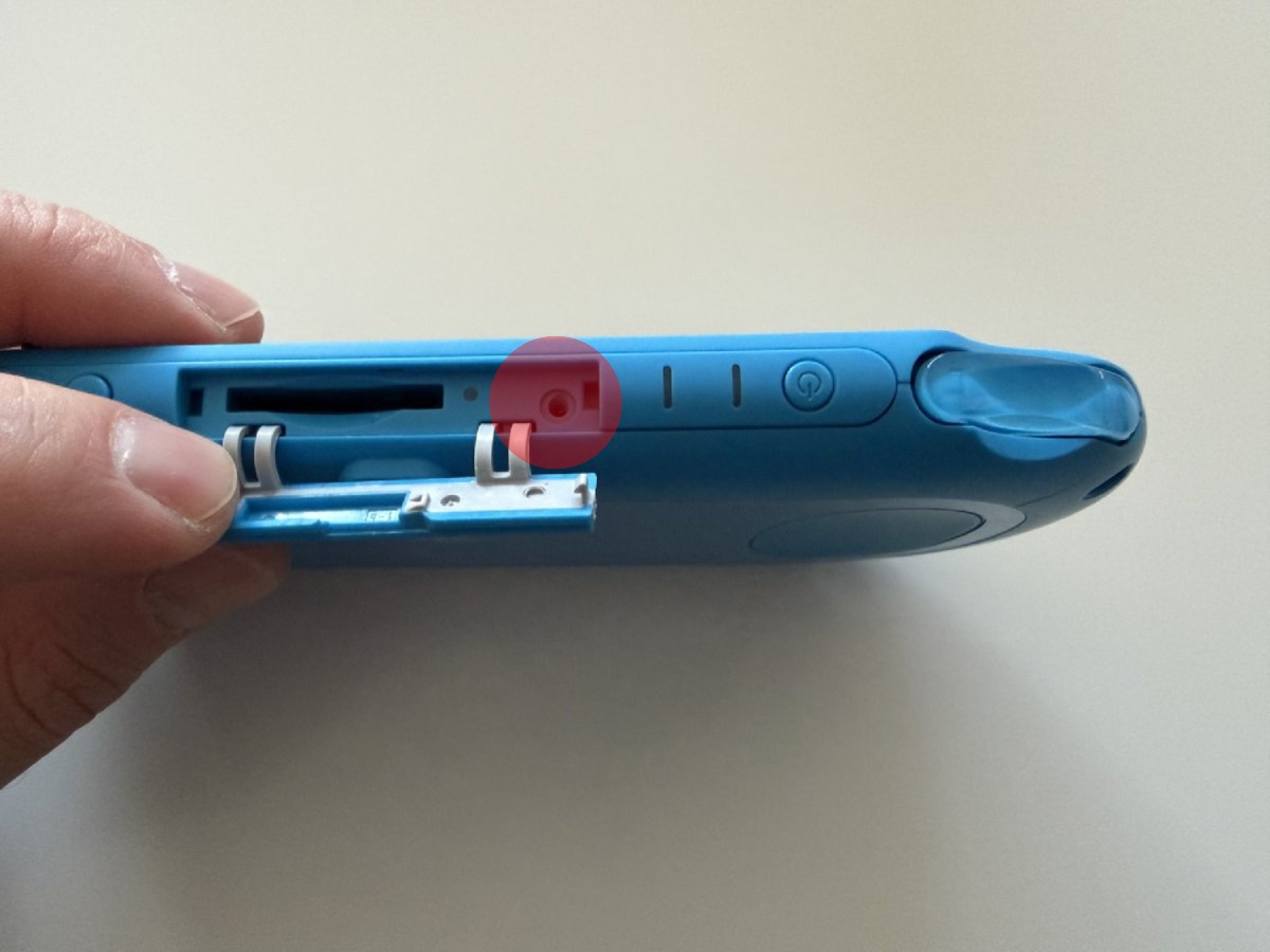
Turn off the device completely and make sure the battery level is low. Remove the memory card or game card. We start by removing the 7 Phillips head screws around the case as shown in the photos.
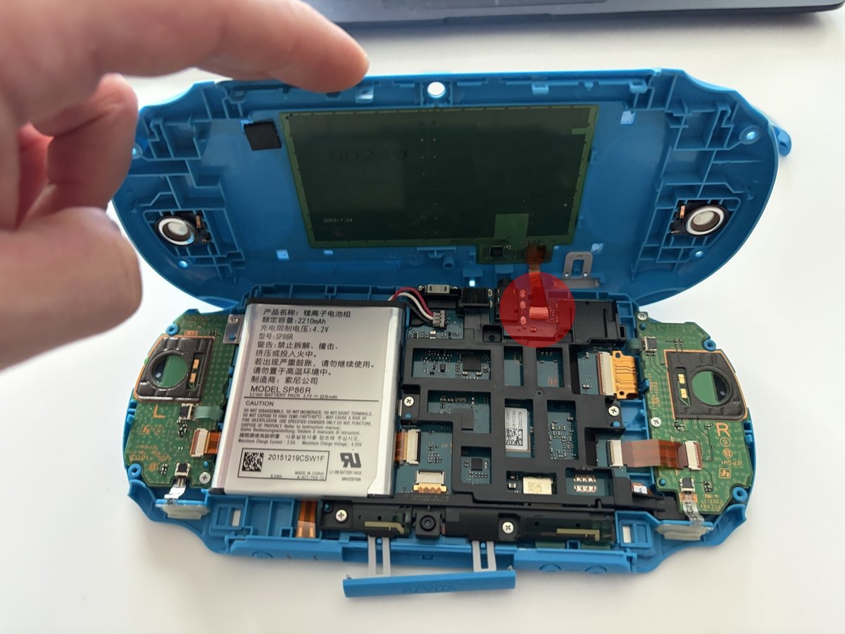
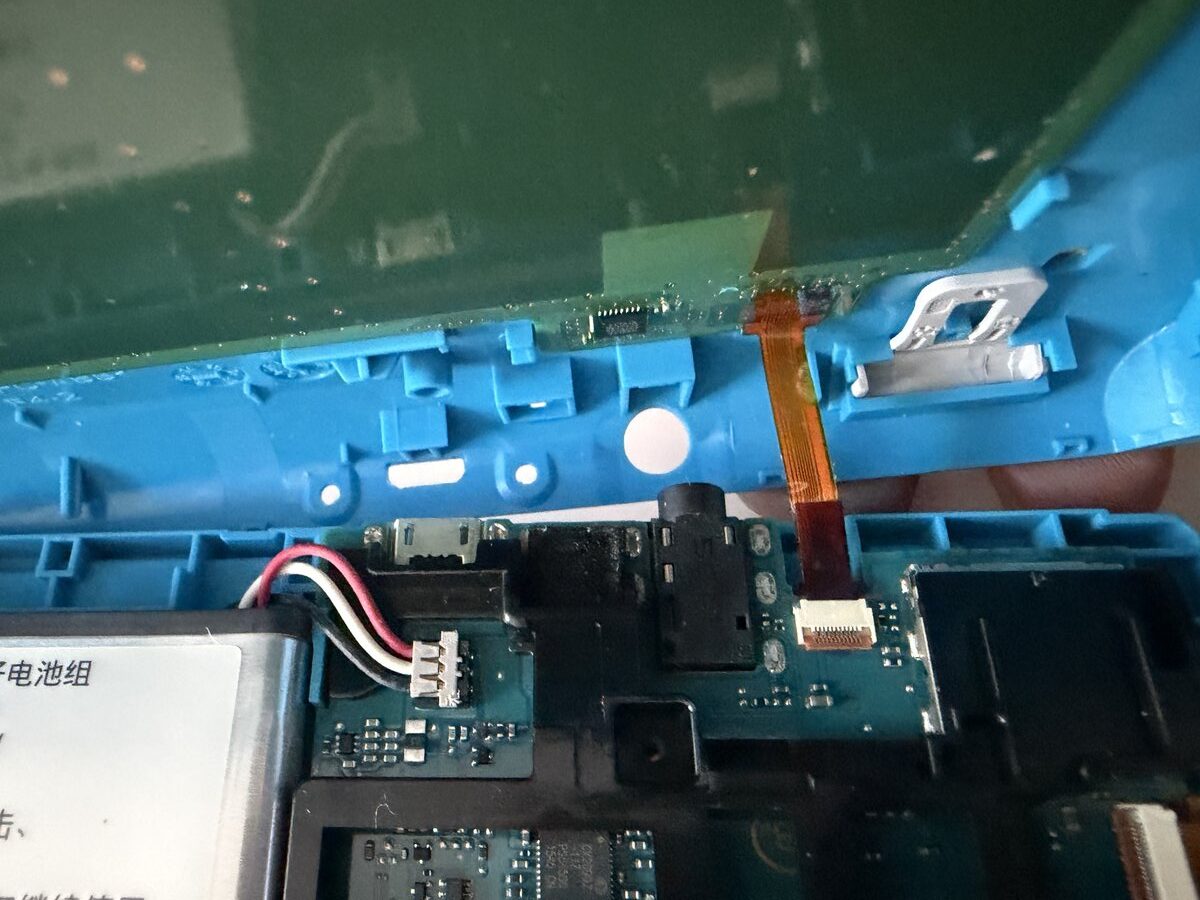
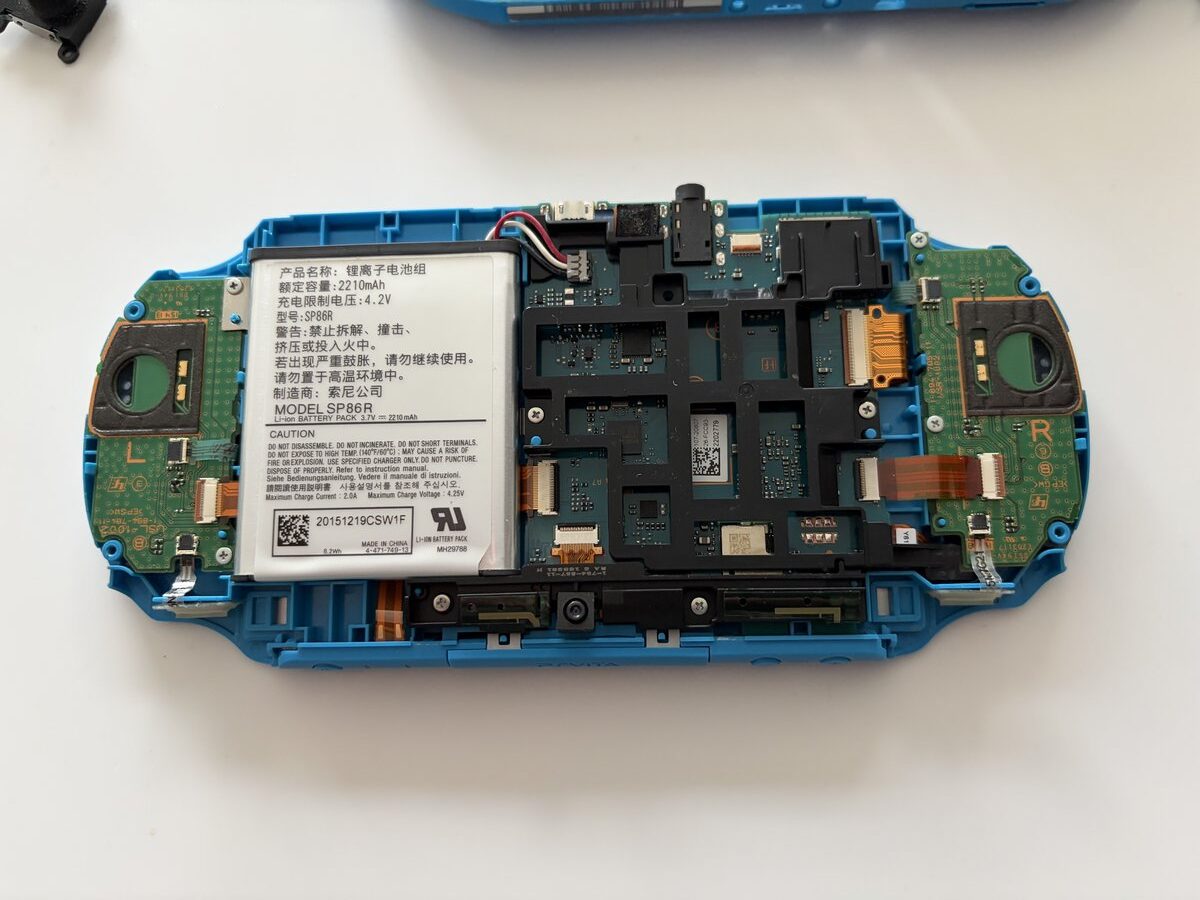
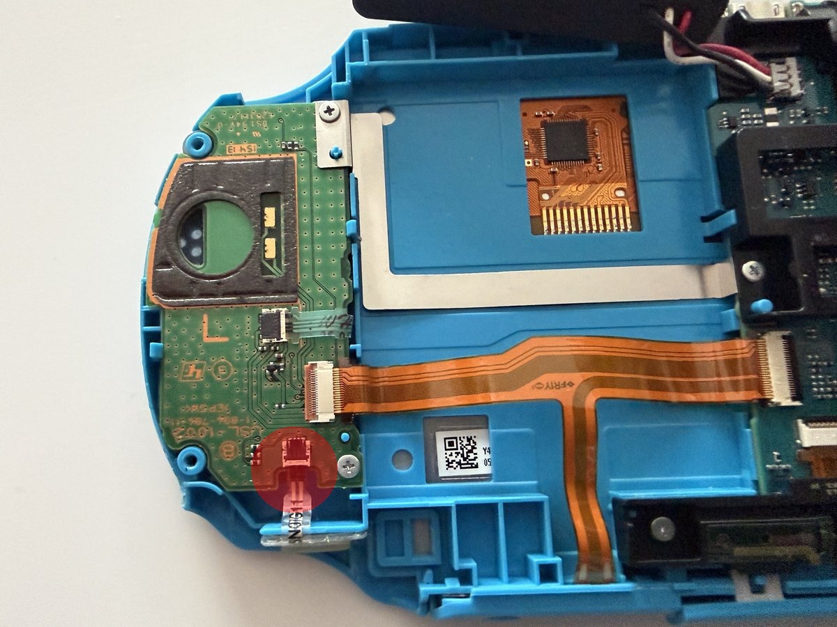
After removing all the screws, we carefully separate the back cover with a plastic opening tool. Since the clips are quite fragile, it’s important to be slow and patient. When the back cover is opened, the first thing we need to do is disconnect the flex cable that connects the rear touch panel to the PCB. To do this, you need to lift the brown clip located at the back of the connector upward. On the left side, you can see the 2210mAh Li-ion battery (Model: SP86R), the main board in the center, and the joystick module PCBs on both sides.
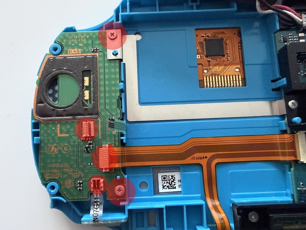
To remove the left joystick module, we first need to carefully disconnect three flex cables. The flex cable connectors are the locking type, so we lift the brown and black clips on the back of the connectors to 90°. We also remove the two Phillips screws that attach the PCB to the case and separate the PCB from the case. There’s one Phillips screw holding the joystick module in place. We remove that too, place our new module, and reverse all the steps.
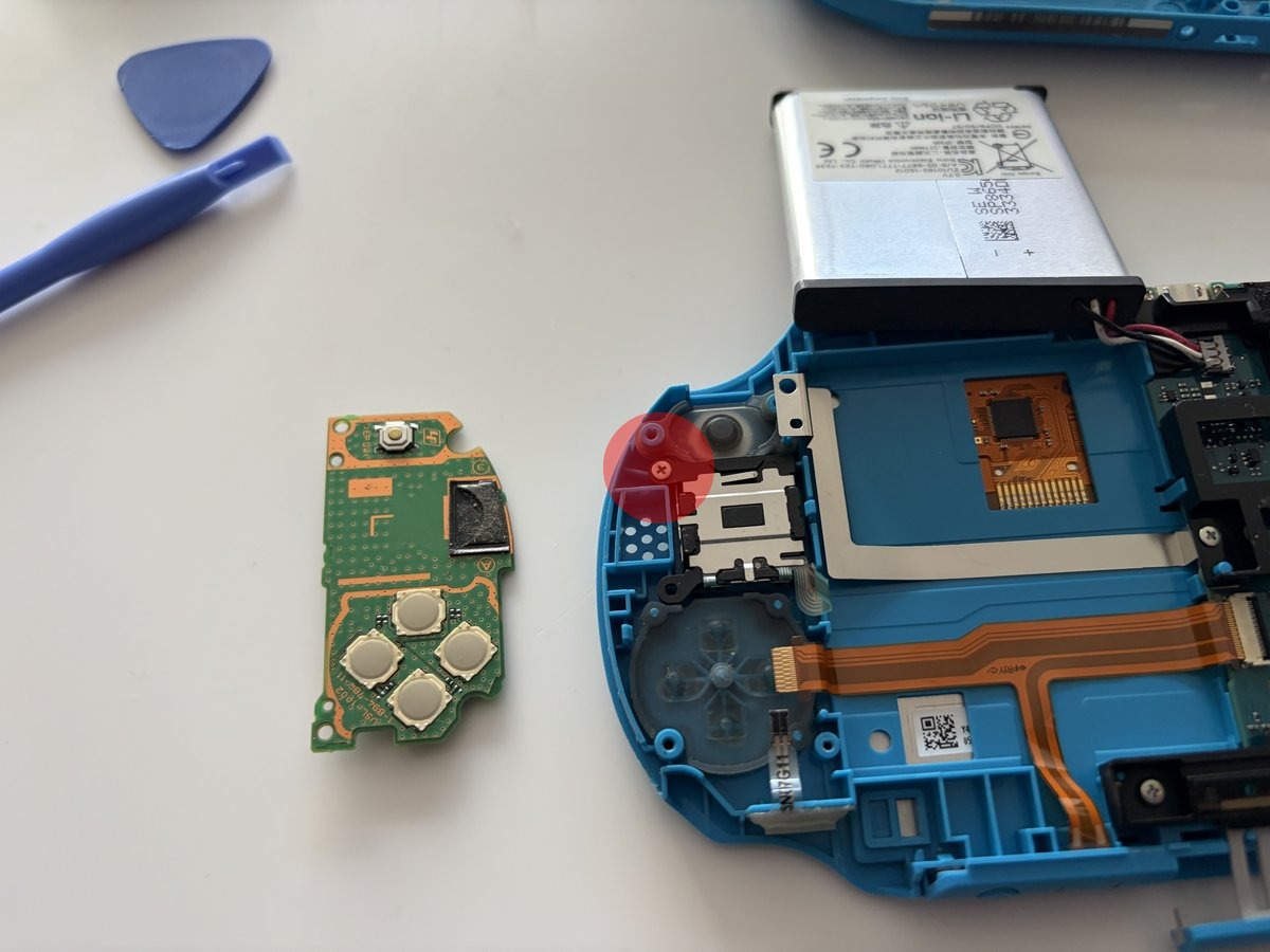
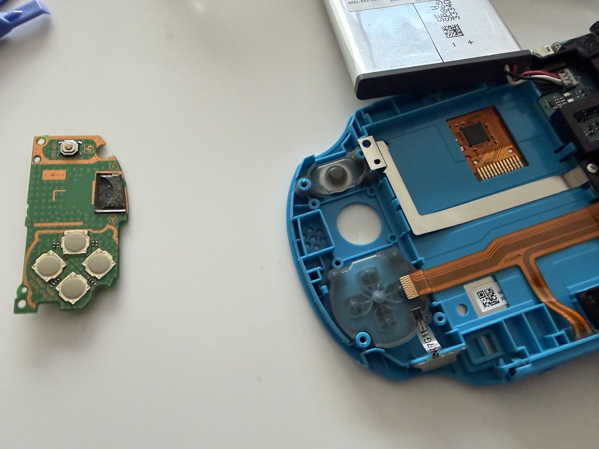
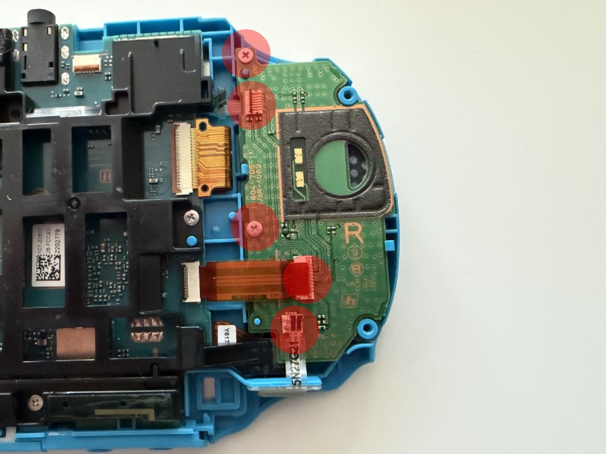
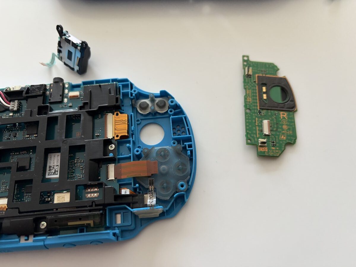
The right joystick module is removed in a similar way. On this side, there’s the action buttons (△○✕□) and the R button PCB.
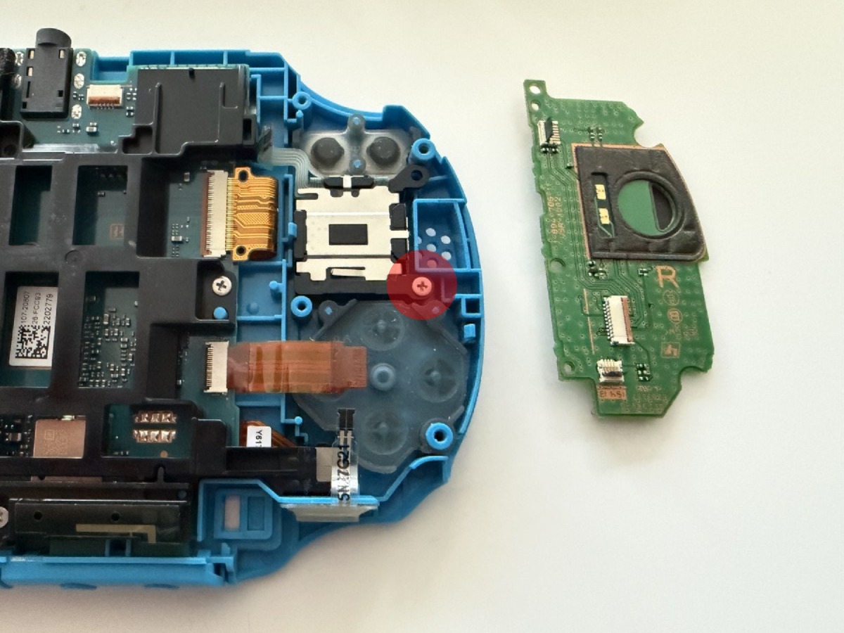
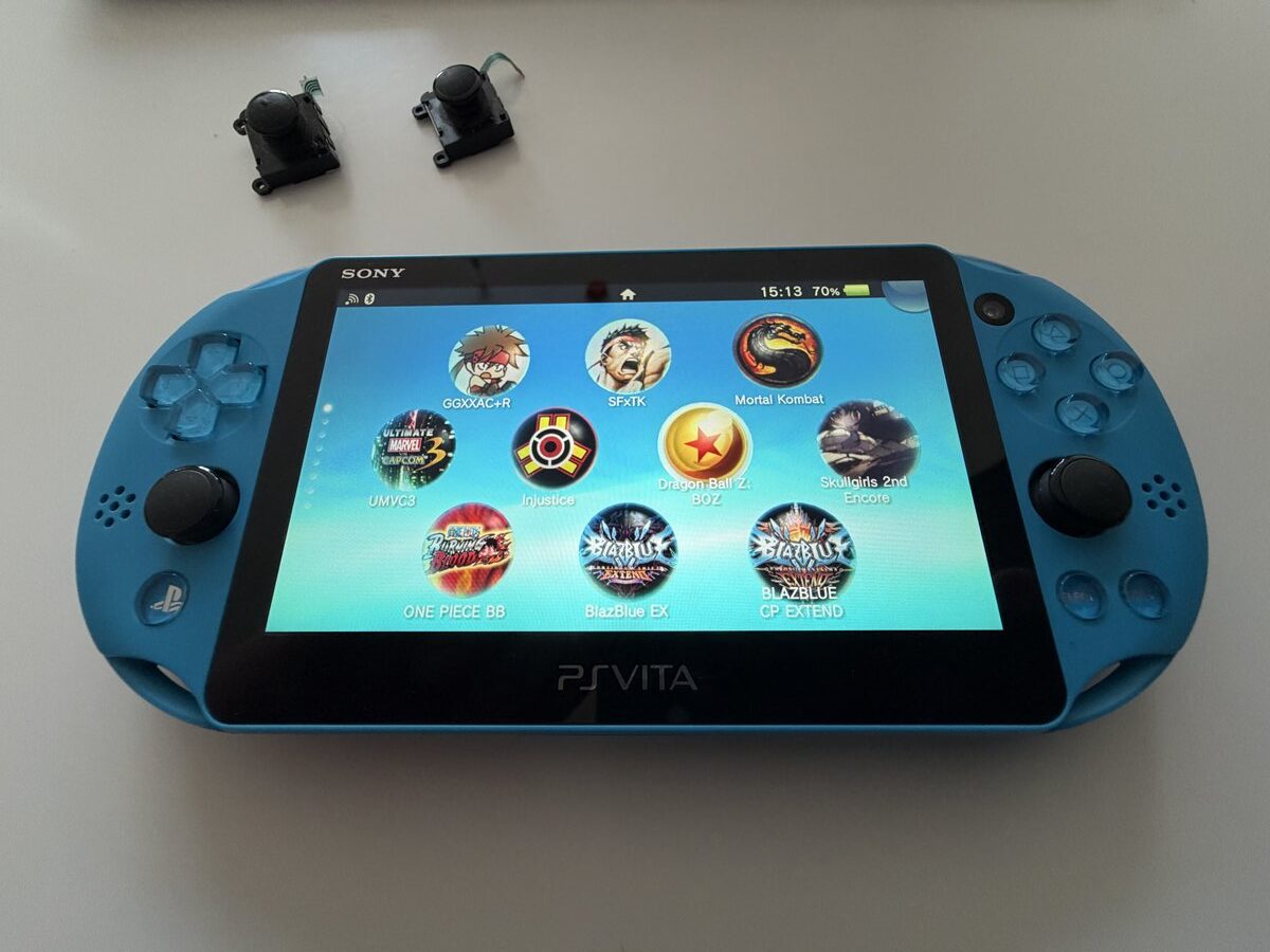
Make sure the flex cables are properly connected, otherwise you might have to open the device a second time like I did. We reassemble by reversing all the connection steps, and the device is ready to use.
Leave A Comment